


Published Aug 3rd, 2020, 8/3/20 6:25 pm
- 1,615 views, 2 today
- 134 downloads, 0 today

28
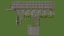
After some time, I have finally gotten to this one. Created back in 2013 as a part of the PoweredCube project, it represented its main graphical output. A big screen with the access to individual pixels has the following characteristics:
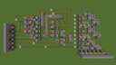
We will use a table to better imagine how things work. It basically represents the monitor input port depicted in the last image:
Once reset signal is equal to 1, all pixels will turn off. If write signal is set to 1, it will write current data value to a pixel addressed by yaddr (Y coordinate) and xaddr (X coordinate) signals. Left bottom corner of the screen is equal to (0, 0).
Hope you all are doing well! ;-)
- 32x24 pixels (768 pixels in total)
- Clear the whole screen signal
- Simple control interface (read below)
We will use a table to better imagine how things work. It basically represents the monitor input port depicted in the last image:
| reset | data | yaddr[5] | xaddr[5] | write |
Once reset signal is equal to 1, all pixels will turn off. If write signal is set to 1, it will write current data value to a pixel addressed by yaddr (Y coordinate) and xaddr (X coordinate) signals. Left bottom corner of the screen is equal to (0, 0).
Hope you all are doing well! ;-)
| Progress | 100% complete |
| Tags |
4557132
2


 SpintextTheLawyer
 ICanGamez
 ScotsMiser
 Kypickle
 Ww2guru73
 ShelLuser
 TheMountaineer
 hotsuop
 TheRedDemon
 SoulBadger

 Bertoxx

 Kareemofficial
 cranzag
 ILoveMinecraftt123
Create an account or sign in to comment.
(Just asking because me and my friend just did it... so I guess that answers you're question... :)
Quite big, clean wiring (although personally I would prefer to have some color coding going on).
By the way, is the input of 'yaddr' and 'xaddr' in binary?
Ad yaddr, xaddr: yes, they are encoded in binary (5 bits each coordinate). Just out of curiosity; what alternatives come to your mind? :-)
+ one line per x-coordinate & one line per y-coordinate -> example 10x10 pixels means 10 x-coordinate lines and 10 y-coordinate lines. Only were they intersect you can write/input goes through.
- input mechanism of say 10 buttons, press one & the old one is flushed out
- up/down counter per coordinate
- hook them up to tripwires or pressureplates (= same amount of pixels).
Hope it makes some kind of sense. Or fly through the PMCview3D on my old submission
https://www.planetminecraft.com/project/paint-system/
(note1, if I recall it doesn't work due to some missing objects in the hoppers for the timer-clocks to work properly
note2, it only contain the latest version, I could try dig up the original save that shoudl work + has the older versions)
ps. as you might have noticed, I am bit rusty in the terms of all the gates and such. It has been some years I worked extensive with those.
The paint system looks interesting but right now I do not have much time to examine it more deeply. Furthermore, I am focused on processors now.
Nevertheless, I like that you did not use command blocks in the map. I personally do not like them since they are transforming hardware problem to a software problem while being seen as a hardware solution then (if you know what I mean). And that's a different level of abstraction.
and it uses X, Y cords... even bigger outch!!!
then clear function... now I'm stuned...
I mean the RAM needed for that is insaine!!!
I like it...
1+ DIAMOND
100% agree xD
> and it uses X, Y cords... even bigger outch!!!
How it should be done then? Just curious. Please note that it must be able to draw individual pixels (buffered/unbuffered don't mind).
> I mean the RAM needed for that is insaine!!!
RAM? If you mean the screen buffer, that's 768 bits = 96 bytes. It is not that much. :-)
Anyway, thank you man! :-)